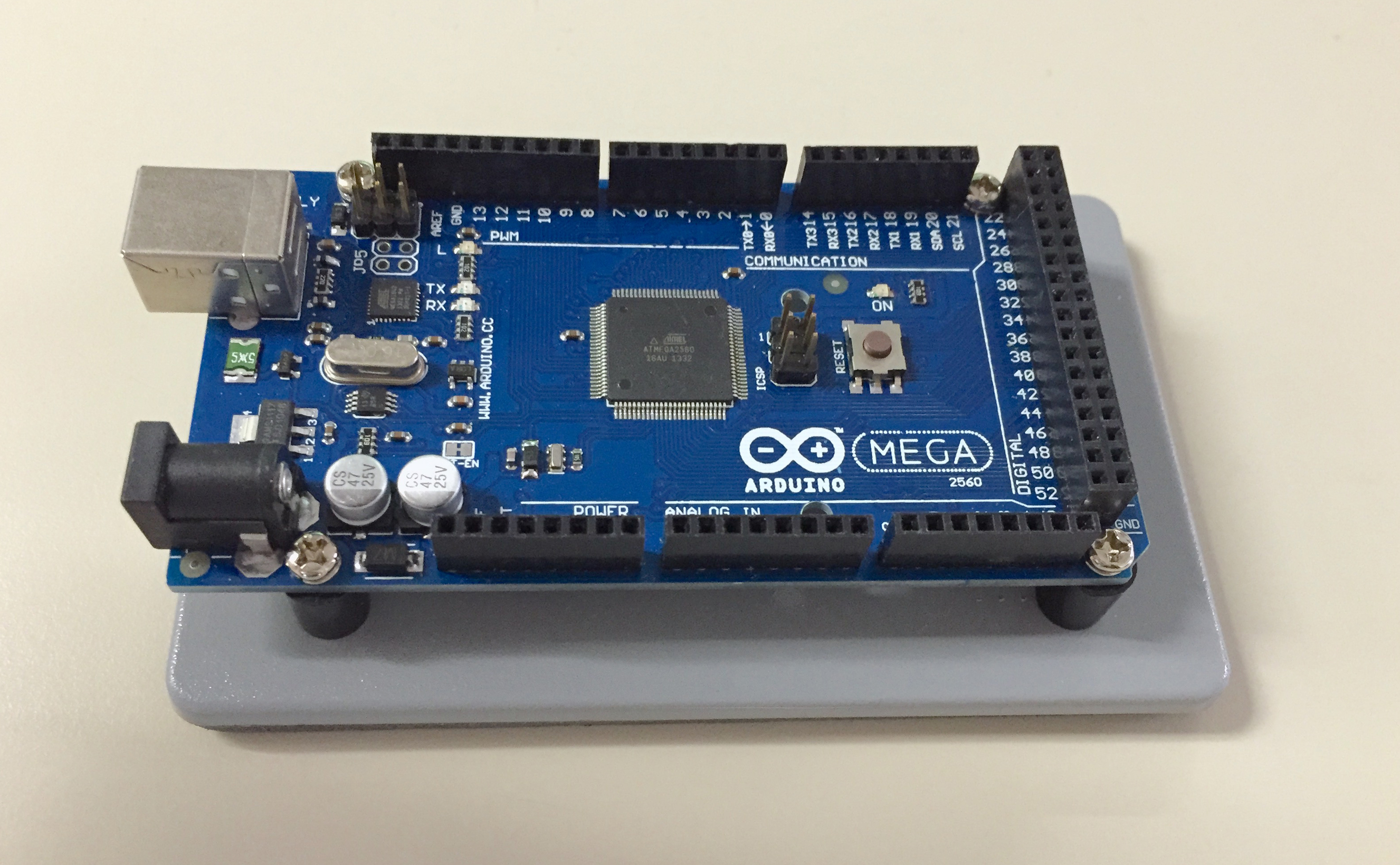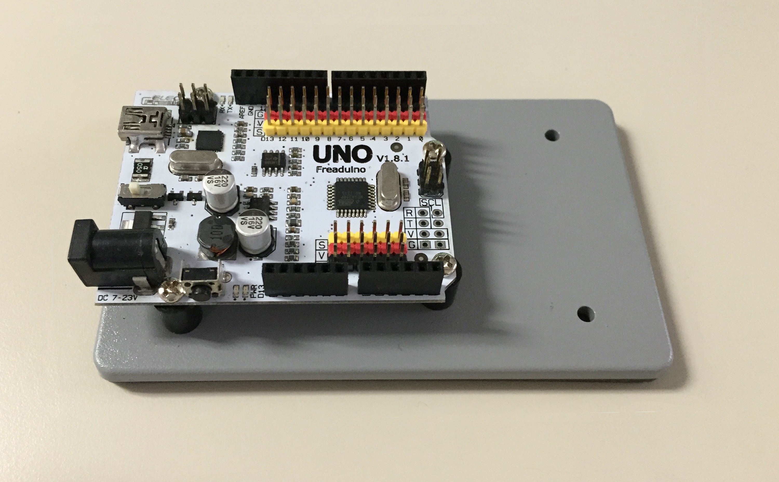
These electrical box covers, found in home improvement and hardware stores, make excellent bases for Arduino boards and prototyping breadboards. The covers have a neoprene weather seal on the back, which keeps a sliding Arduino or breadboard from scratching any surface it may be on. The covers are available as single- or double-gang and in white or gray colors. (I use white for breadboards and gray for PCB devices.) The outer surface has a molded pattern similar to the orange-peel paint texture that you may see on antique items.
I used Radio Shack insulated standoffs (part number 2761381) for most of the boards. The plastic ends of the standoffs were notched as needed to avoid conflicting with soldered pins protruding from the underside of each board. When possible I used existing holes for the mounting screws, but felt no reticence to drill new ones.
Double-sided tape was used to adhere the breadboards to their bases. I added small breadboard power supply PCBs to each breadboard. Because these were supported only by their inserted pins, I cut nylon spacers to the correct height to support them. The spacers are screwed to the base, but not to the power boards themselves. Instead, the power boards just sit on the tops of the spacers. Note that the large breadboard was too long for one cover plate, so two plates were cut to the desired length. No gluing was needed, because the double-sided tape used to mount the breadboard holds perfectly well.
I like several things about using these covers as bases:
The Arduino, breadboard, or other device is held securely in place
The foam gasket on the back of the cover protects surfaces and keeps things from sliding
The bases look rather nice, I think, and give a consistent look to all the devices
-- Stan Cleveland, McMinnville, Oregon
Back to CodeMunki HomeTop view of Freaduino and base.
Top view of Mega and base.
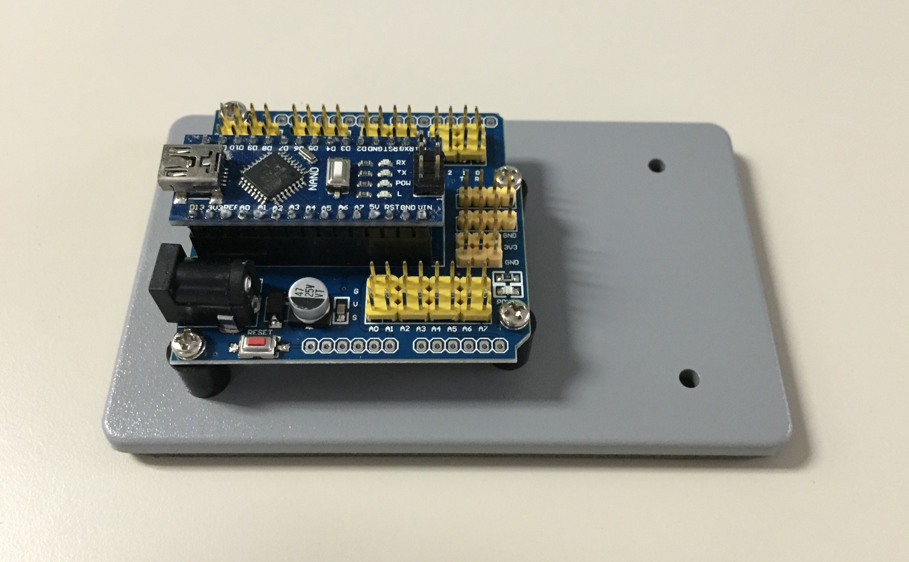
Top view of Nano, I/O extension, and base.
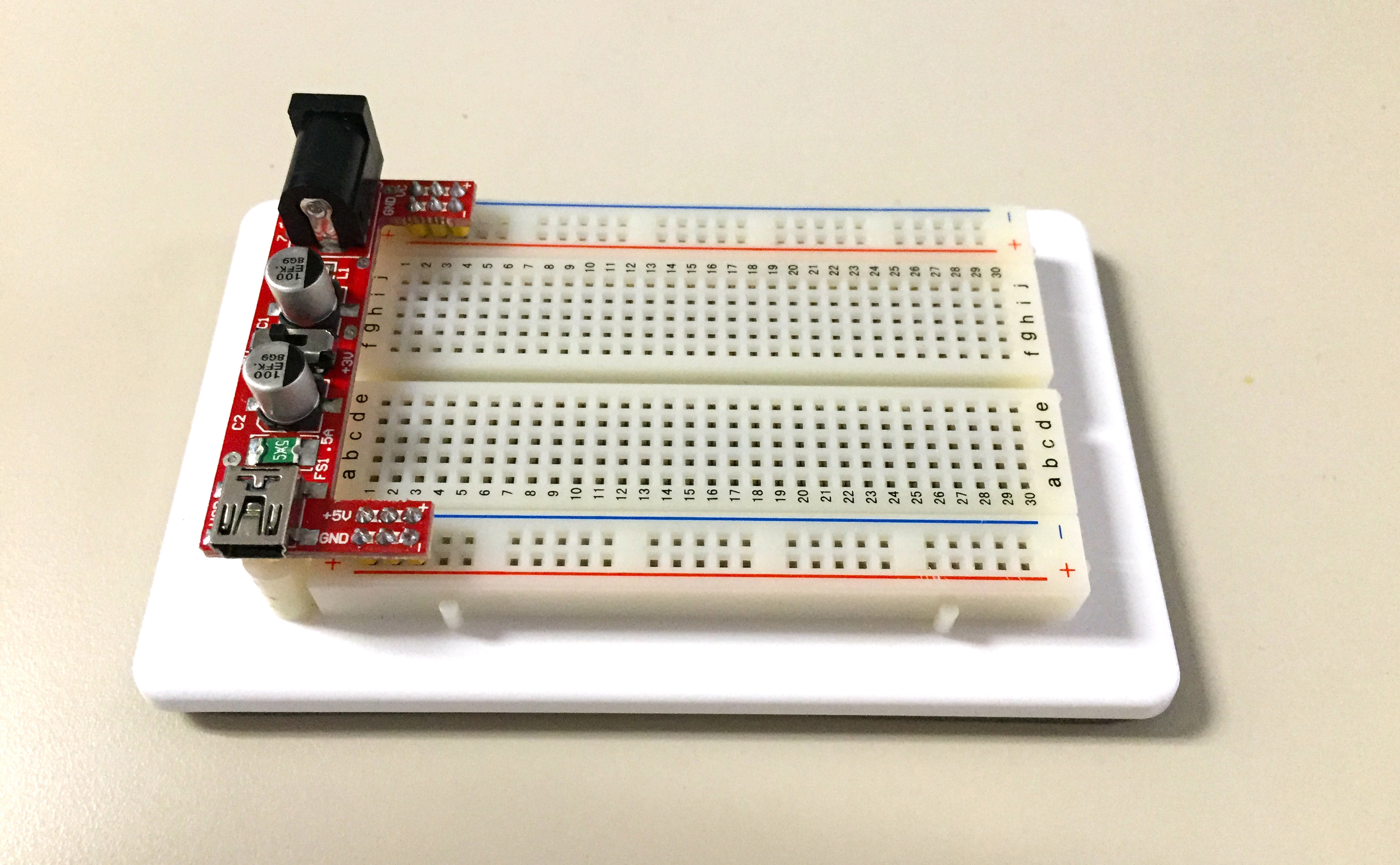
Top view of small breadboard, power supply, and base.
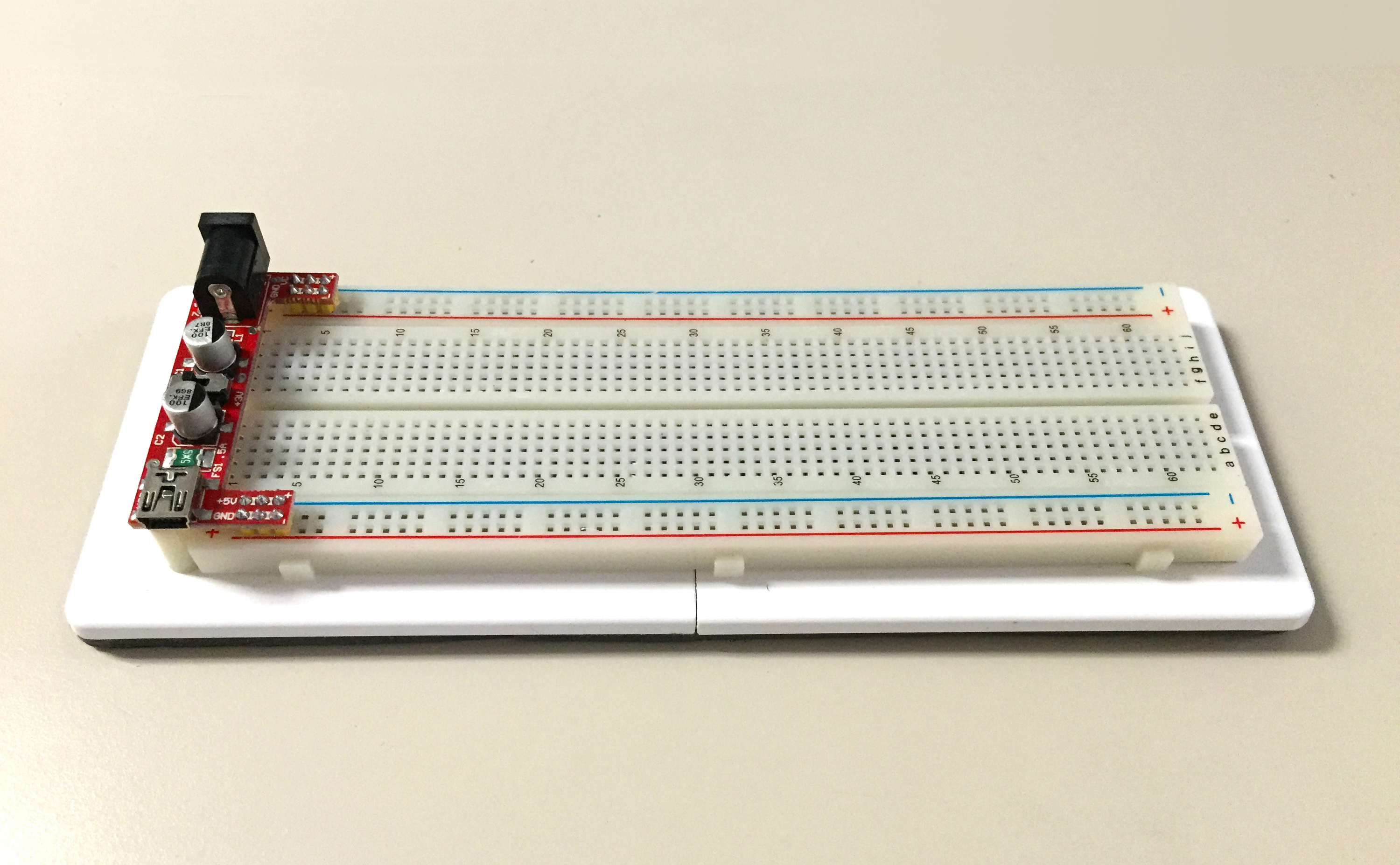
Top view of large breadboard, power supply, and base.
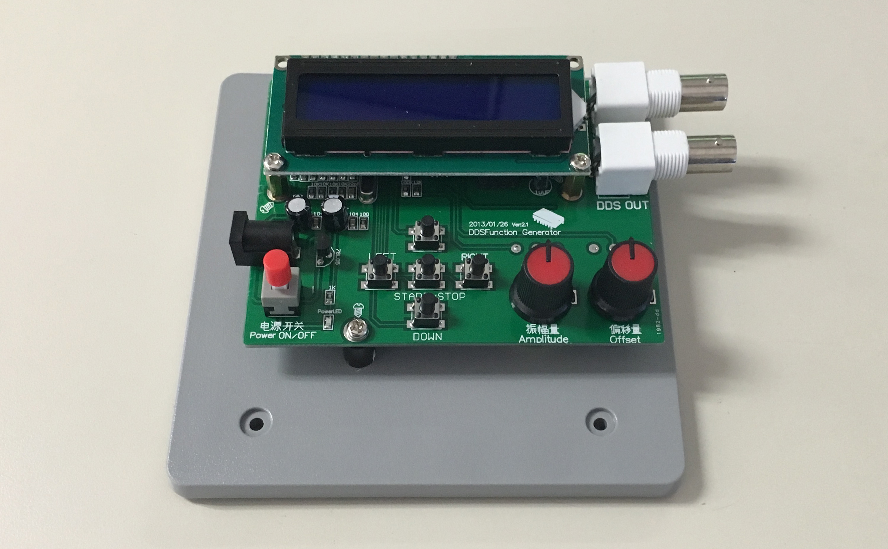
Top view of DDS function generator and base.
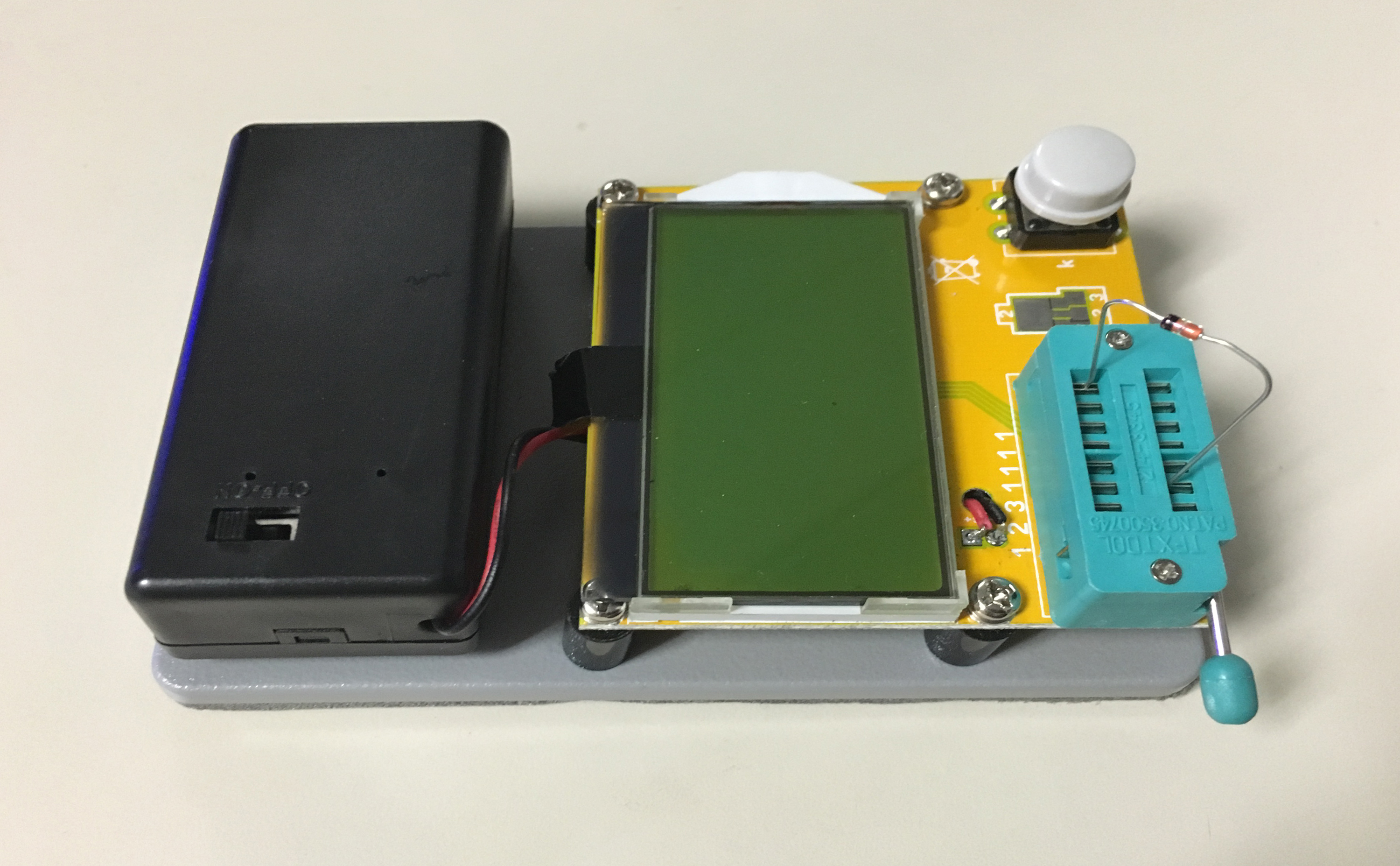
Top view of component tester with battery box and base.
The battery box is held in place with double-sided foam tape.
The battery box wires are soldered to the PCB and replace the original clip-on 9V connector.
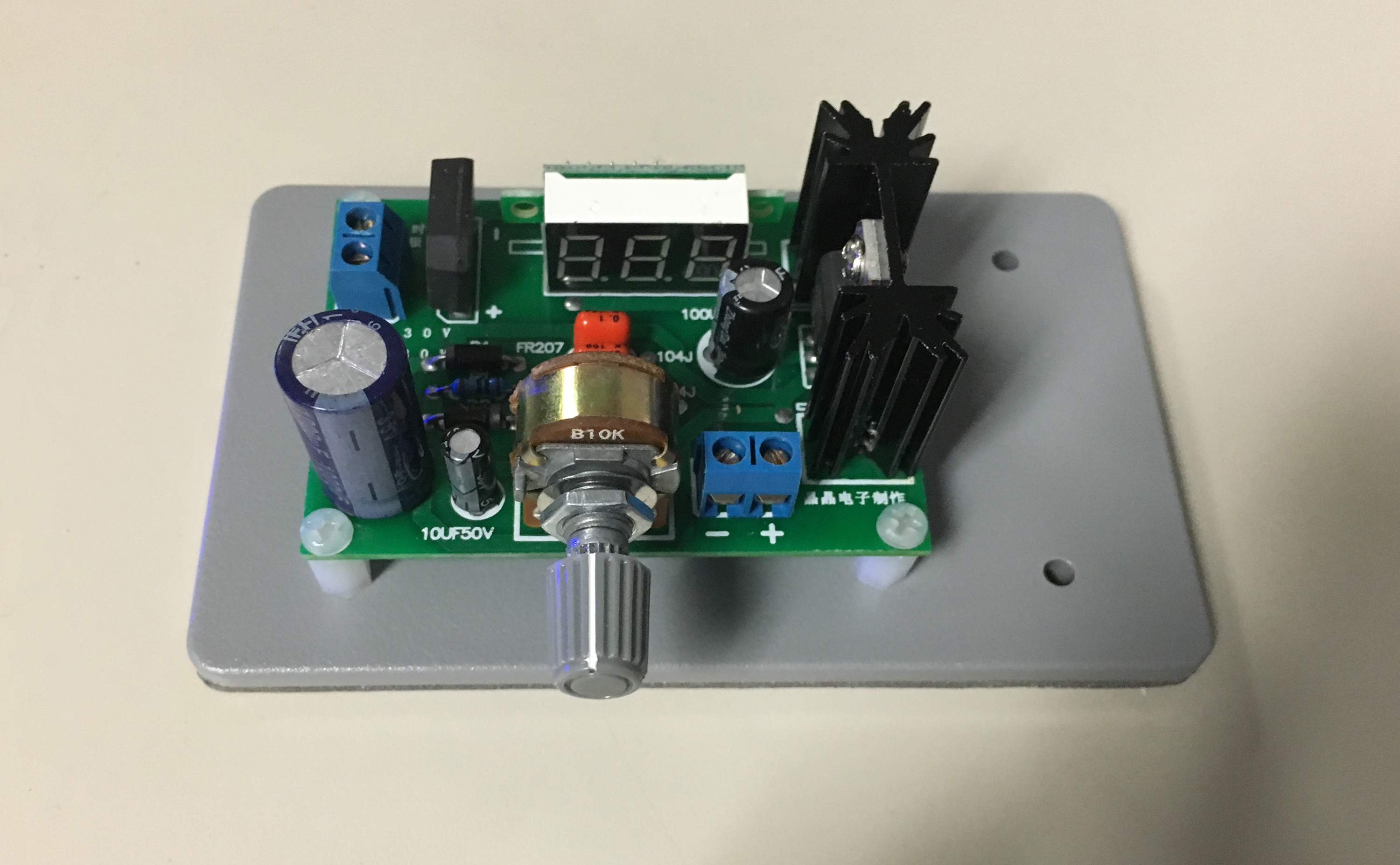
Top view of variable regulated DC power supply and base.
This board and the next one are attached to the base with nylon hex standoffs and screws.
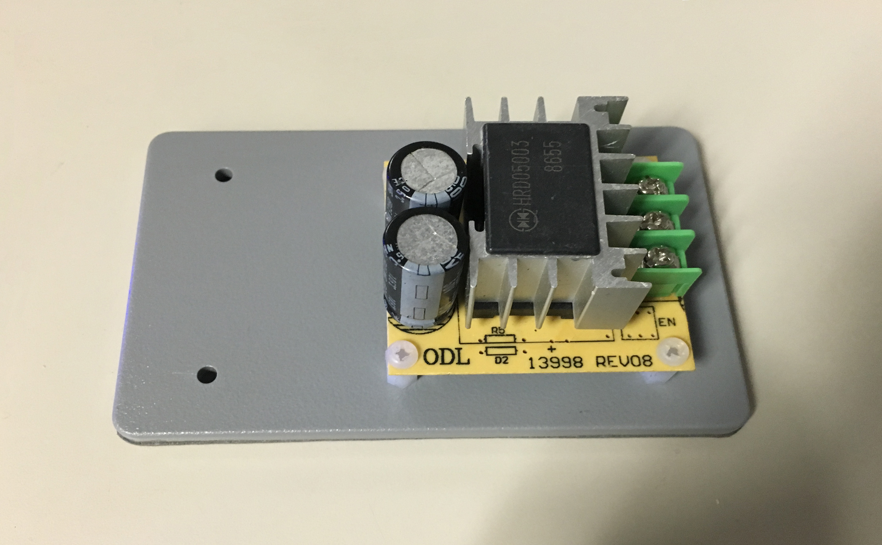
Top view of DC-to-DC step down converter and base.
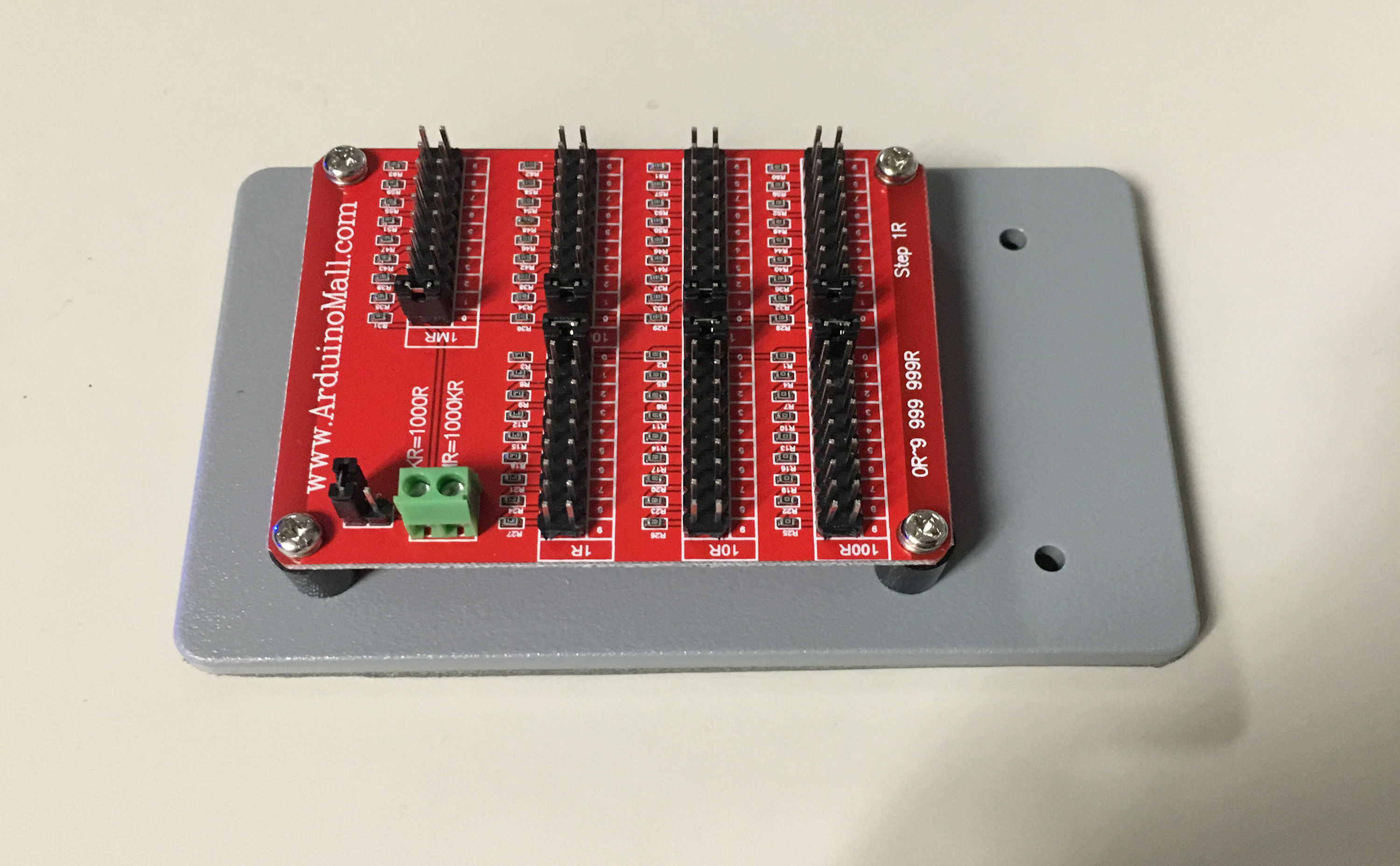
Top view of seven-decade resistance board and base.
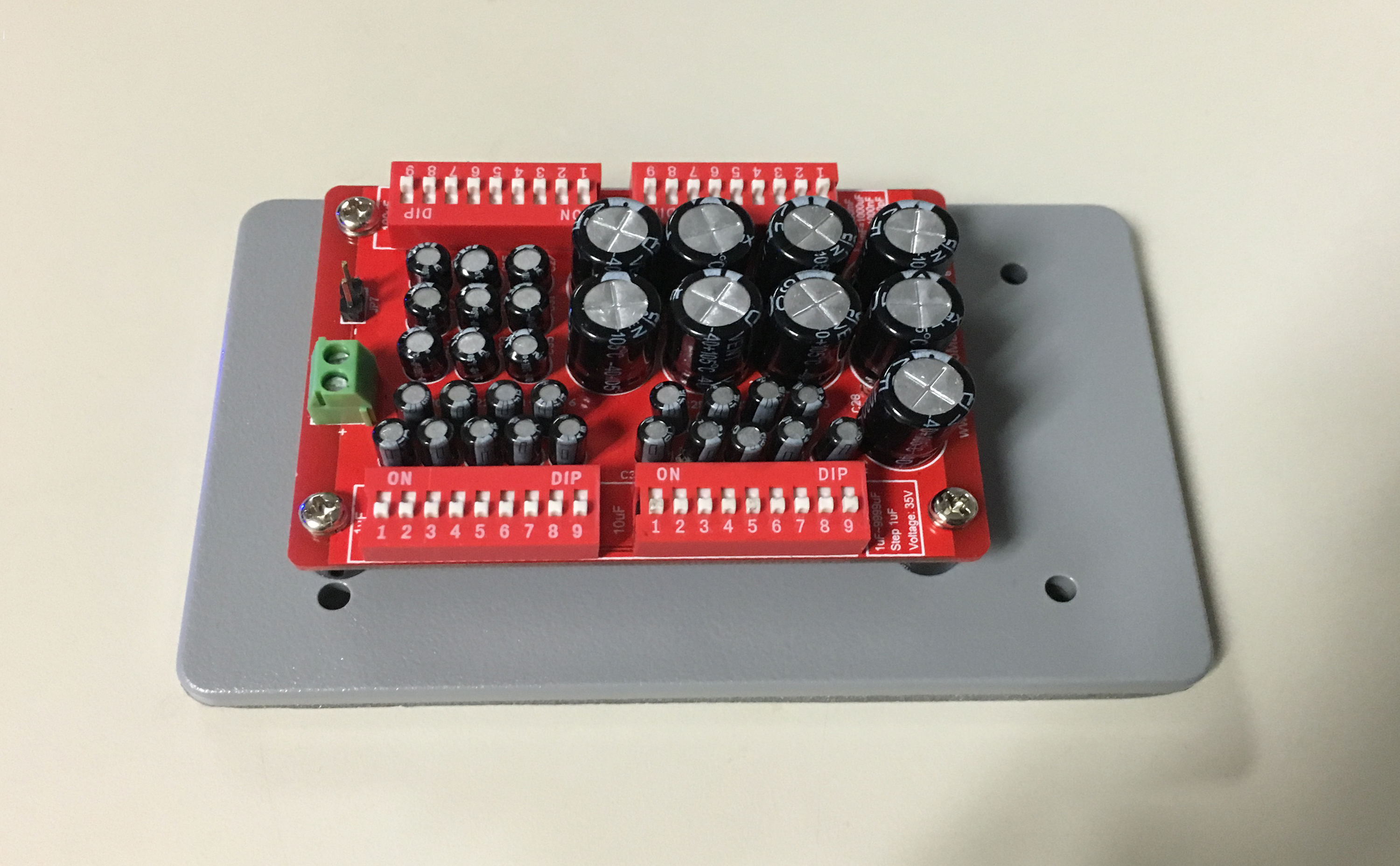
Top view of four-decade capacitance board and base.
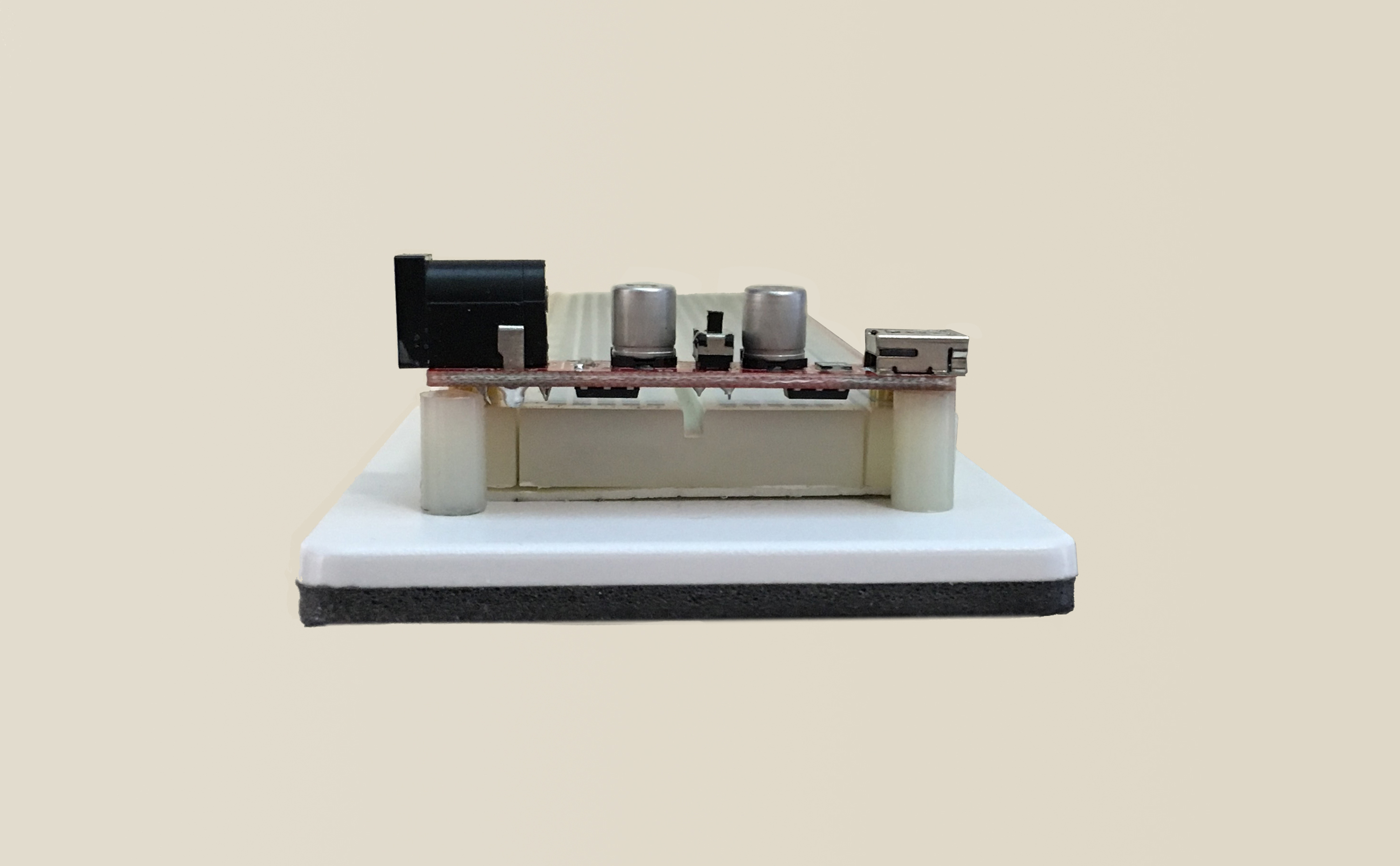
End view of large breadboard and base, showing power supply supports.
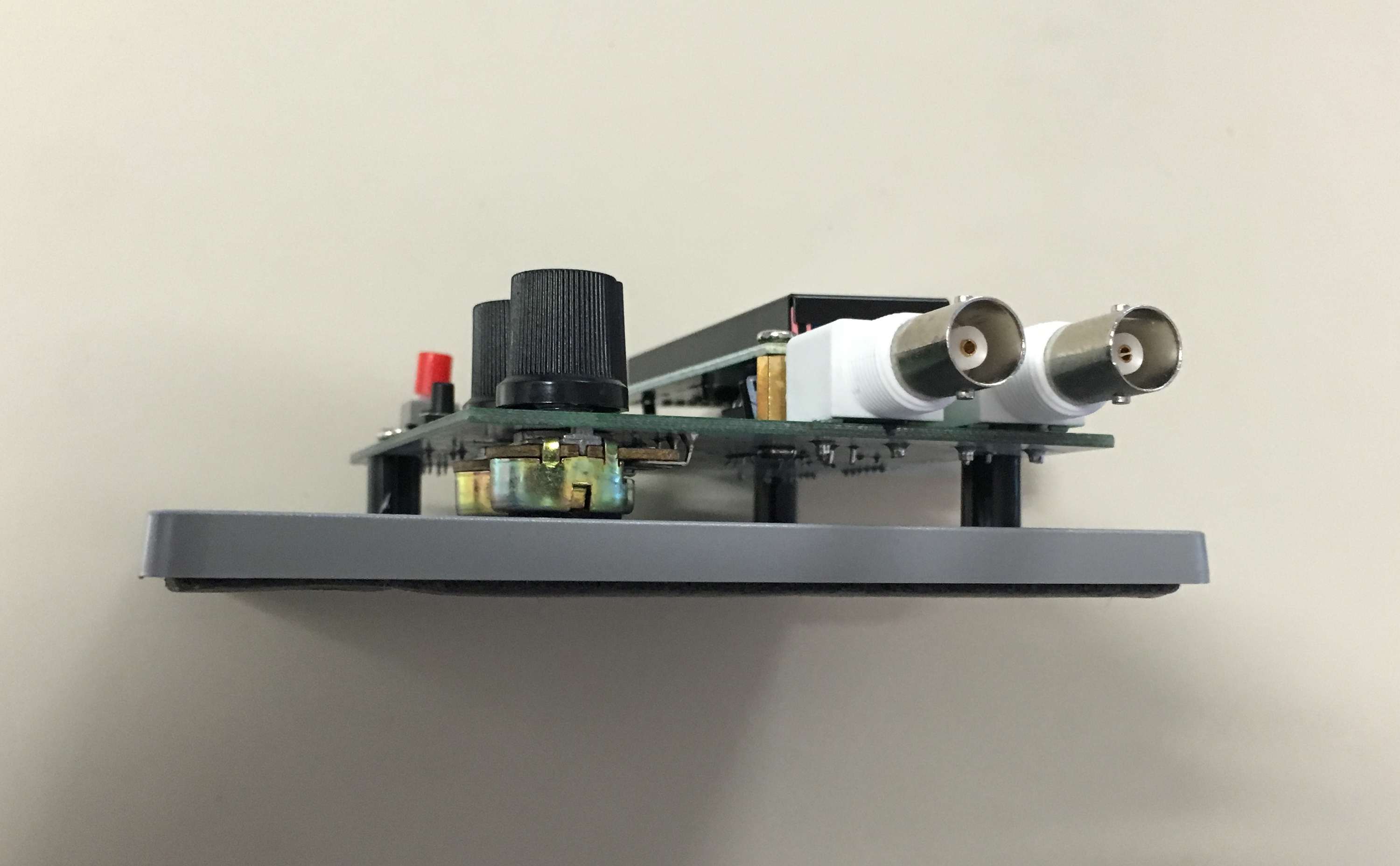
End view of DDS function generator and base, showing supports, one of which is a potentiometer.
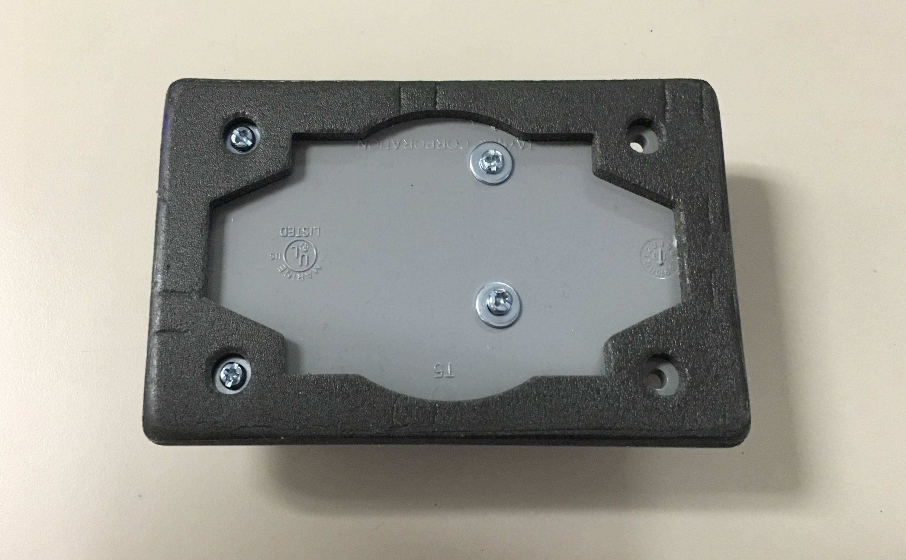
Bottom view of Freaduino base.
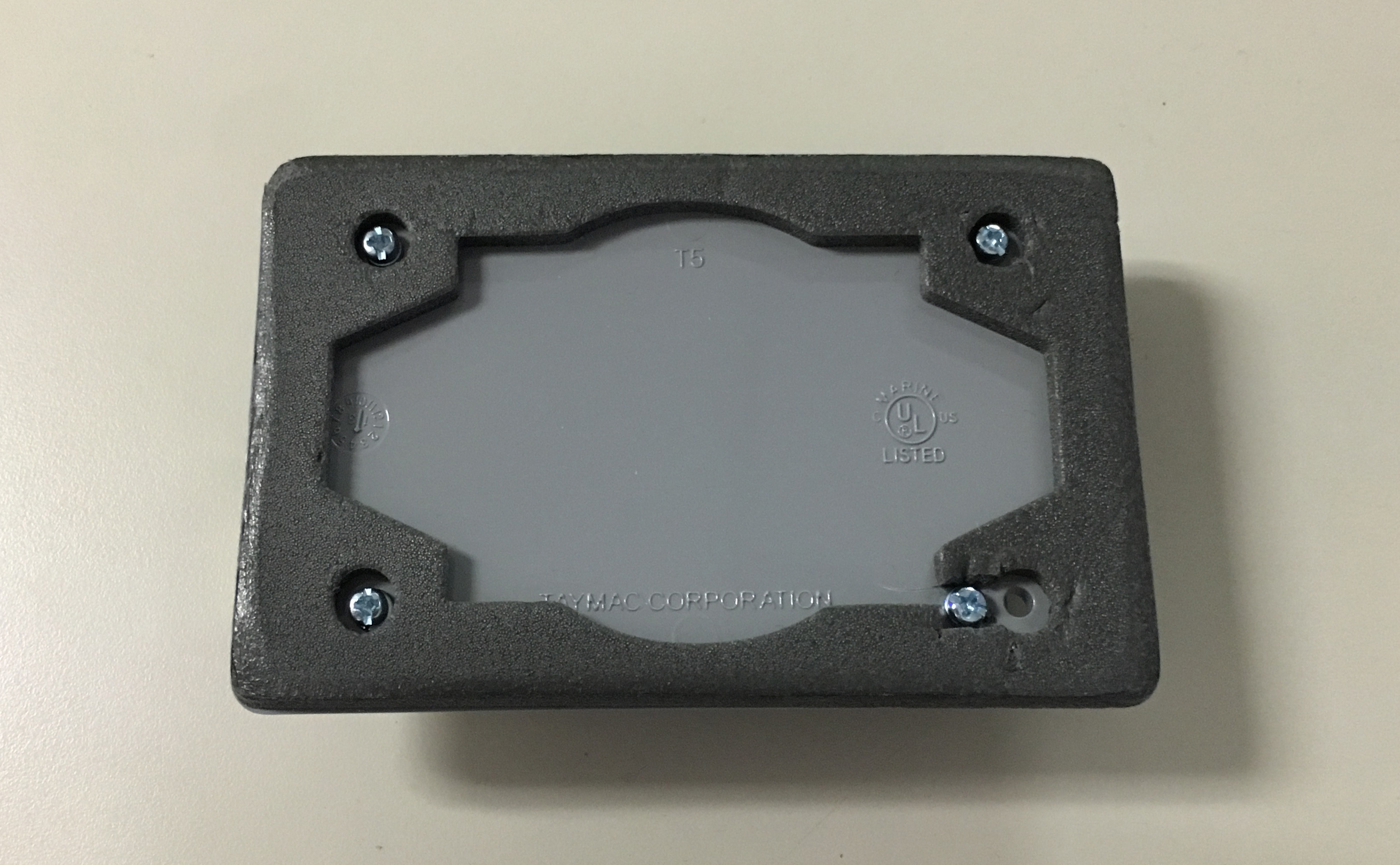
Bottom view of Mega base.
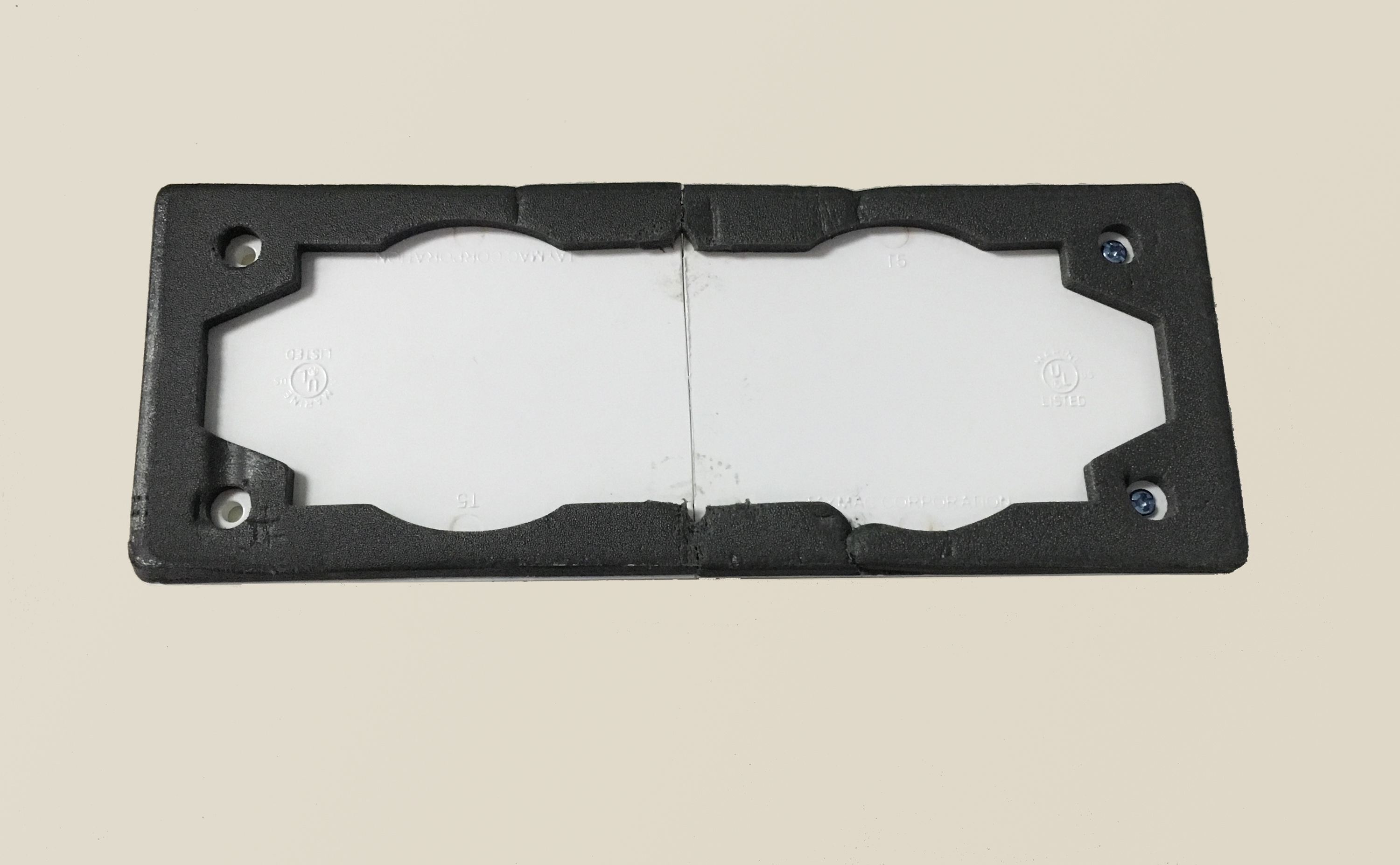
Bottom view of large breadboard base.
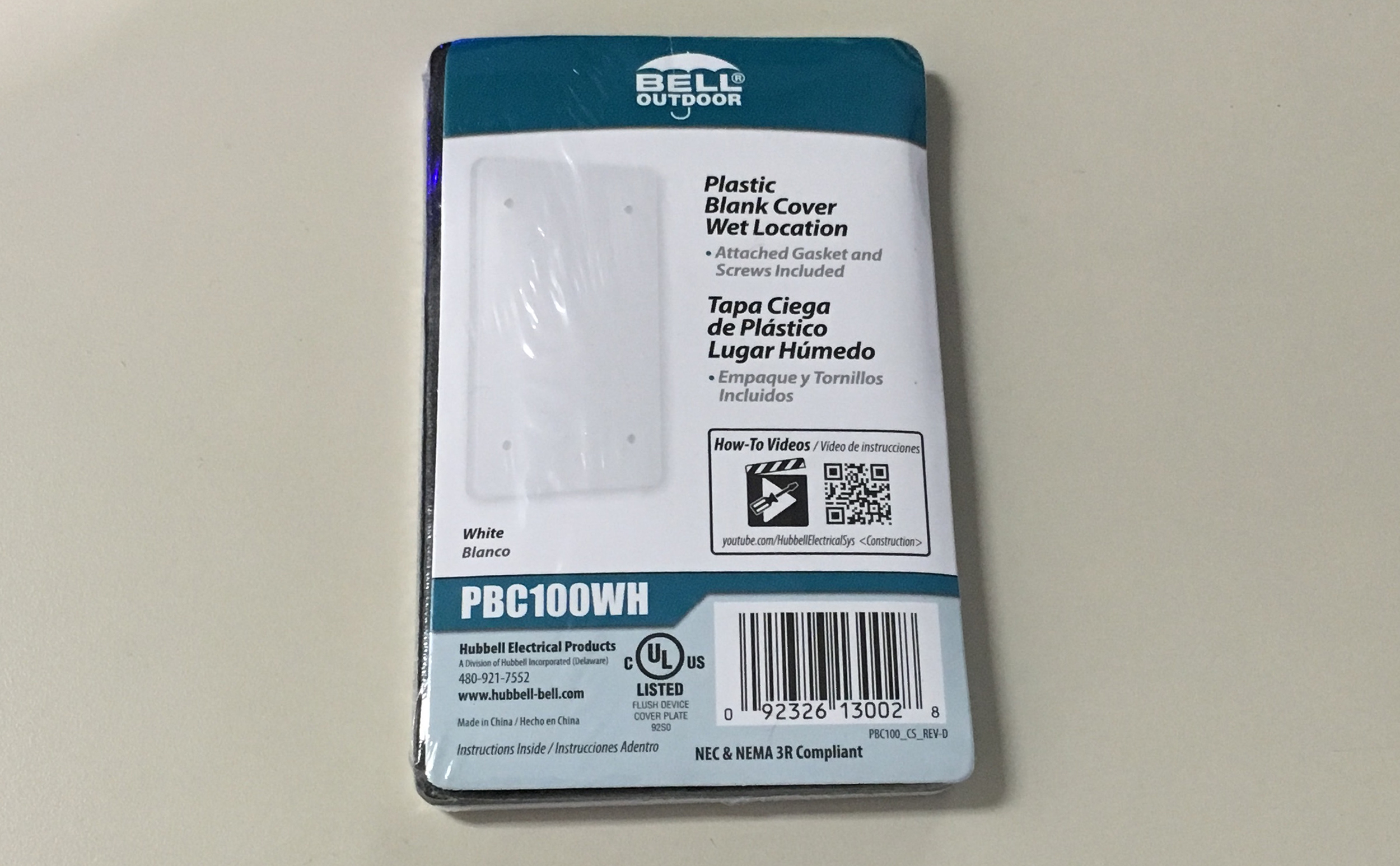
Package for small, white cover plate.
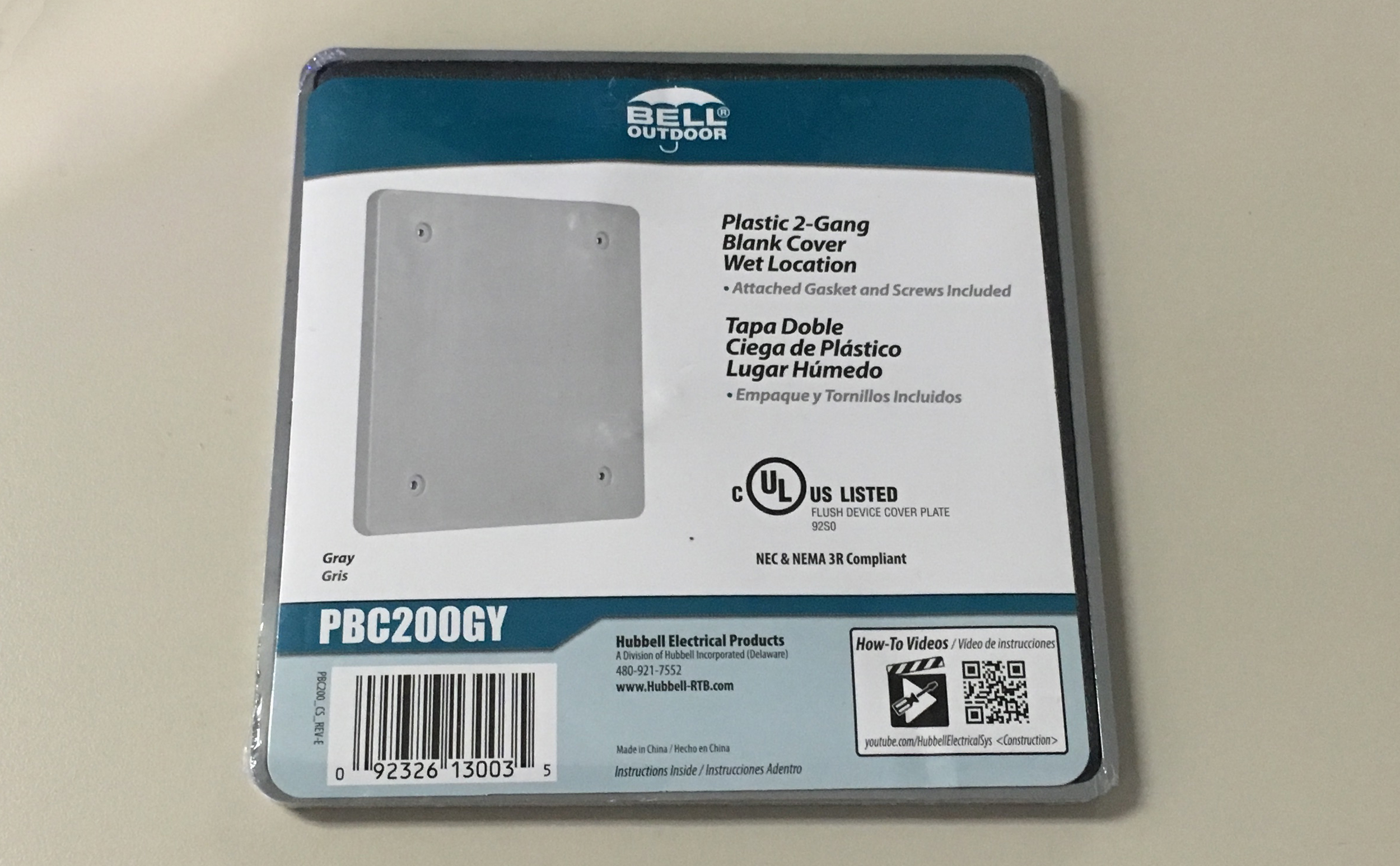
Package for large, gray cover plate.